Appendix A4. Symmetry Information
Symmetry Information displays detailed information about the space-group symmetry of the selected crystal, and additionally renders schematic diagrams of the symmetry elements and general positions in the style of International Tables for Crystallography Vol. A.
In IPAnalyzer, this sub-window is opened from the Crystal window (the CrystalControl used in 4. Practical procedures for geometric calibration and in 6. Find Parameter (brute force)).
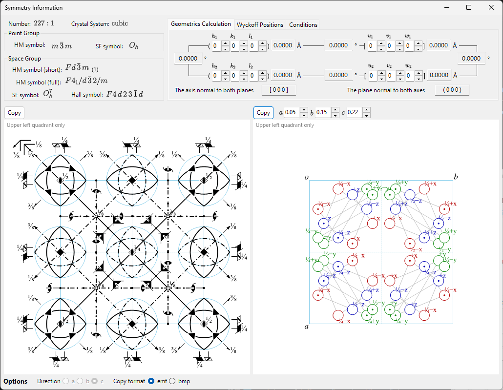
The window is divided into a space-group identity area (top left), a calculation/table area with tabs (top right), and two schematic diagrams (bottom).
Keyboard & mouse shortcuts
This window has no special key or mouse combinations. F1 opens this manual page, and the two Copy buttons place the symmetry-element diagram and the general-position diagram on the clipboard (as a bitmap, or as a vector EMF when EMF is ticked).
Space-group identity
The top-left panel lists, for the current space group:
- Number (1–230) and the setting index
- Crystal System
- Point Group : Hermann–Mauguin (HM) and Schoenflies (SF) symbols
- Space Group : HM short symbol, HM full symbol, SF symbol, and Hall symbol
Geometrics Calculation
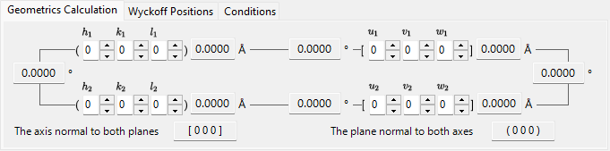
Enter two crystal planes \((h_1, k_1, l_1)\), \((h_2, k_2, l_2)\) or two direction indices \([u_1, v_1, w_1]\), \([u_2, v_2, w_2]\) to obtain:
- the d-spacing of each plane / the length of each axis,
- the angle between the two planes (or two axes),
- the direction index normal to both planes and the plane index normal to both axes.
These calculations respect the metric of the current unit cell.
Wyckoff Positions
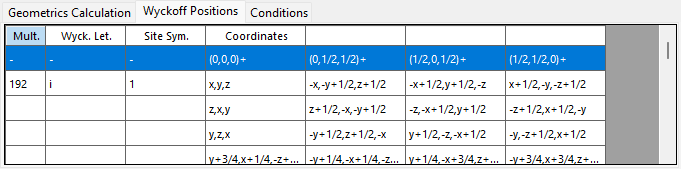
Lists every Wyckoff position with its multiplicity, Wyckoff letter, site symmetry, and whether it is a general or special position. For centred lattices, the lattice translation vectors are shown in the header row.
Conditions
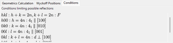
The reflection conditions arising from the lattice centring and from the glide/screw symmetry operators.
Symmetry-element & general-position diagrams
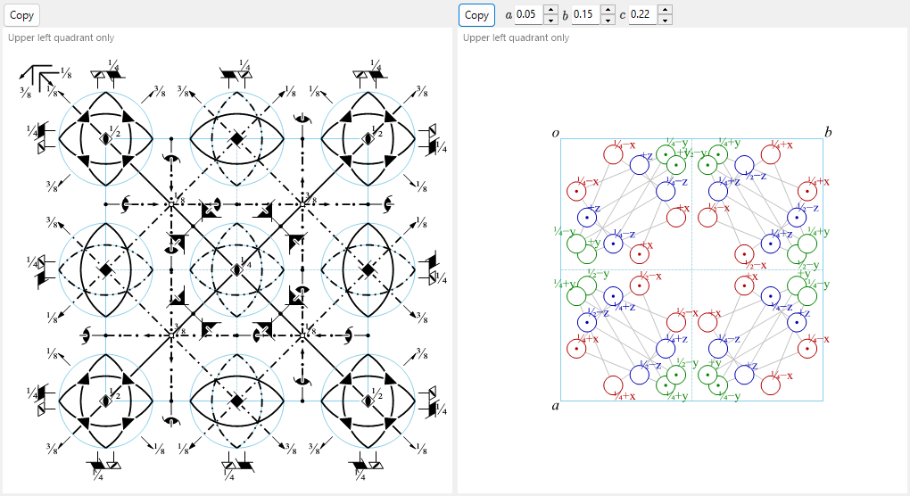
The two panels at the bottom reproduce the schematic symmetry diagrams of the space group in the notation of International Tables for Crystallography Vol. A.
- Symmetry elements (left): rotation/screw axes, mirror/glide planes, and inversion centres/rotoinversion points are drawn with the conventional graphical symbols.
- For the \(F\) lattice of the cubic system, only one-eighth of the unit cell (the upper-left quadrant only) is shown.
- General positions (right): the general equivalent positions are plotted as circles (a comma denotes a mirror image), annotated with their fractional coordinates.
- For the cubic system only, auxiliary lines connect the three circles related by a three-fold rotation axis.
Controls below the diagrams:
- Direction (
a/b/c) : choose the crystal axis to project along. - Copy each diagram to the clipboard as a vector image (EMF) or raster image (BMP); EMF can be ungrouped and edited in PowerPoint.
See also
- Appendix top
- 4. Practical procedures — geometric parameter calibration using a standard crystal.
- 6. Find Parameter (brute force)