Appendix
This appendix summarizes the theoretical background of the geometry and algorithms that IPAnalyzer uses when converting a two-dimensional diffraction image (Debye–Scherrer rings) into a high-accuracy one-dimensional profile. For operating procedures and how to use each feature, refer to the main manual (0. Overview, 4. Practical procedures, etc.). Here we explain, with equations, the coordinate-system definitions, coordinate transforms, parameter-determination methods, and integration algorithm behind it.
The content is based on the legacy document doc/IPAnalyzerAlgorithm.pdf bundled in the distribution package and on the current implementation.
Structure of the appendix
- A1. Detector geometry and coordinate transforms — definition of the right-handed coordinate system, the rotation matrices that describe the IP tilt (\(\varphi,\ \tau\)), and correction of the pixel shape (\(\mathrm{PixSizeX},\ \mathrm{PixSizeY},\ \xi\)).
- A2. Parameter determination — calibration of camera length, wavelength, pixel size, and IP tilt using a standard material (two-distance method, two-line method, ellipse fitting).
- A3. Image integration — the area-partitioning algorithm that distributes pixel intensities into angular steps.
Coordinate system (common reference figure)
Each of the following pages assumes the same coordinate system as a common premise. The origin is the direct spot on the IP (the point where the beam intersects the IP), the \(Z\) axis is the beam propagation direction, and the sample is located at \((0,\ 0,\ -\mathrm{CL})\).
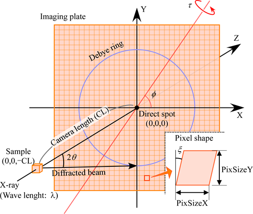
Main parameters
| Symbol | Name | Meaning |
|---|---|---|
| \(\lambda\) | Wave Length | Wavelength of the source. Known for characteristic X-rays; for synchrotron radiation it varies with the monochromator position and must be determined each time. |
| \(\mathrm{CL}\) | Camera Length | Distance between the sample and the origin (direct spot). The sample position is \((0,0,-\mathrm{CL})\). |
| \(\varphi,\ \tau\) | Tilt Correction | Tilt of the IP relative to the optical axis (\(Z\) axis). \(\varphi\) is the azimuth of the tilt axis in the XY plane, and \(\tau\) is the rotation angle about that axis. |
| \(\mathrm{PixSizeX},\ \mathrm{PixSizeY},\ \xi\) | Pixel Size | Represents a pixel as a parallelogram. \(\xi\) is the offset of the readout laser's scan starting point (distortion angle). |
These values are set on the IP Condition tab of the property window (see 2. Property windows).