Appendix A1. Detector geometry and coordinate transforms
This page defines, with equations, the coordinate system, IP tilt correction, and pixel-shape correction that IPAnalyzer uses to map pixel positions on a flat detector (IP, CCD/CMOS) to diffraction angles. For an overview of the coordinate system, see also the appendix top page and 0. Overview.
Coordinate system and parameters
IPAnalyzer consistently uses a right-handed coordinate system internally.
- The point where the X-ray or electron beam intersects the IP (the direct spot) is taken as the origin \((0,0,0)\), and the \(Z\) axis is aligned with the beam propagation direction.
- Treating the sample as infinitesimally small, the distance between the sample and the origin is defined as the camera length \(\mathrm{CL}\). The sample position is therefore \((0,\ 0,\ -\mathrm{CL})\).
- The \(X\) axis is aligned with the scanning direction of the readout laser when the IP is not tilted (the rightward direction of the image). The \(Y\) axis therefore points downward on the screen.
- A diffraction ring with cone angle \(2\theta\) is observed, on an untilted \(XY\) plane, as a perfect circle of radius \(\mathrm{CL}\tan 2\theta\).
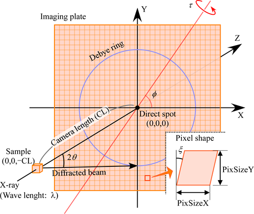
Free rotation of a 3D object inherently requires three axes, but because the Debye-ring distribution is invariant under rotation about the \(Z\) axis, the \(X\) axis can be chosen arbitrarily. This removes one degree of freedom, so the IP tilt can be expressed with two variables \(\varphi,\ \tau\).
Correspondence with (WIN)PIP
The legacy software PIP expresses the tilt with a different pair of angles \((\beta,\ \Phi)\). The conversion from \((\beta,\ \Phi)\) to IPAnalyzer's \((\varphi,\ \tau)\) is \((\beta,\ \Phi)\rightarrow(270^\circ-\beta,\ \Phi)\). For details, see "Relationship with (WIN)PIP" in 0. Overview.
IP tilt correction
The tilt of the IP with respect to the optical axis (the \(Z\) axis) is represented by a rotation whose axis is a line passing through the origin and lying in the \(XY\) plane. This rotation can be written as the rotation matrix \(R = R_2\,R_1\,R_2^{-1}\), an operation that rotates by \(\tau\) along (\(R_1\)) an axis that has been rotated by \(\varphi\) about the \(Z\) axis (\(R_2\)).
This is equivalent to a rotation by angle \(\tau\) about the unit vector \(\mathbf{n} = (\cos\varphi,\ \sin\varphi,\ 0)\) that makes angle \(\varphi\) with the \(X\) axis in the \(XY\) plane, and expanding gives
Forward transform (untilted plane → tilted IP)
A point \(P_1 = (X,\ Y,\ 0)\) on the untilted \(XY\) plane maps to \(P_2 = R\,P_1\) on the tilted IP.
Projection (tilted IP → untilted plane)
What is actually needed is the inverse direction, namely the \(XY\)-plane coordinate that a "pixel observed on the tilted IP" would occupy if there were no tilt. This is given by the central (perspective) projection that finds the point \(P_3\) where the line joining a point on the tilted IP and the sample \((0,0,-\mathrm{CL})\) intersects the \(XY\) plane. Since this is a projective transform with the sample as the center of projection,
results. Because the entire tilt correction is a linear (projective in homogeneous coordinates) transform, the position of each pixel can be computed quickly on a computer.
Pixel-shape correction
The pixel shape of the IP is treated as a parallelogram with length \(\mathrm{PixSizeX}\) along the \(X\) axis, length \(\mathrm{PixSizeY}\) along the \(Y\) axis, and a deviation from a right angle (distortion angle) \(\xi\). A nonzero \(\xi\) means that there is an offset in the start position of the readout laser scan, and this software assumes that this offset is constant along the \(Y\) axis.
The actual coordinate \(P\) of the pixel that is \(\mathrm{PixNumX}\) away in the \(X\) direction and \(\mathrm{PixNumY}\) away in the \(Y\) direction, counting from the central pixel, is given by
By combining this pixel-shape correction with the tilt correction described above, any pixel on a tilted IP can be mapped to its correct position on the untilted \(XY\) plane. This mapping is the basis for the parameter determination in the next chapter and for A3. Image integration.