Spot ID v1
Spot ID v1 detects, fits, and indexes diffraction spots from experimental electron diffraction images. It also supports manual zone-axis search from a numerically entered spot geometry (the former TEM ID).
Main area
Displays the diffraction image. Load images by drag & drop or from the File menu. Right-click or right-drag to zoom.
Mouse operations
| Operation | Action |
|---|---|
| Single left click | Select a spot |
| Double left click | Add a spot |
| Ctrl + left double-click | Add direct spot |
| Ctrl + right single click | Remove spot |
Image adjustments
| Setting | Description |
|---|---|
| Min / Max | Brightness range (also adjustable via track bar) |
| Gradient | Positive or Negative |
| Scale | Linear or Log |
| Colour | Grey scale or Cold-Warm |
| Dust & Scratch | Remove exceptional bright/dark pixels (set range and threshold) |
| Gaussian blur | Apply blur (range in pixels) |
Optics
Enter the incident source, energy/wavelength, camera length, and detector pixel size.
If a dm3/dm4 file (Gatan Digital Micrograph) is loaded, these values are set automatically.
Spot detection and fitting
Press Detect & fit spots to automatically detect diffraction spots and fit them with a 2D Pseudo-Voigt function. Results appear in the table.
Detection options
| Parameter | Description |
|---|---|
| Number | Maximum number of spots to detect |
| Nearest neighbour | Minimum distance between detected spots |
| Fitting range | Radius (pixels) around each spot for fitting |
Table controls
| Button | Action |
|---|---|
| Reset range | Re-set fitting range for all spots |
| Show label/symbol | Overlay labels/symbols on the image |
| Clear all spots | Remove all spots |
| Save / Copy | Export table in tab-separated (Excel) format |
| Re-fit all | Re-fit all spots |
Spot detail window
Check the box to open a detail window showing the selected spot (left) and profiles in four directions (right). Blue = observed data, red = fit.
Index
Press Identify spots to index detected spots against the crystal selected in the Main window.
| Setting | Description |
|---|---|
| Acceptable error | Tolerance for indexing |
| Single grain / Multi grains | Index as single crystal or multiple grains (set max grain count) |
| Show label/symbol | Overlay indexed labels on image |
| Refine thickness and direction | Apply dynamical theory (Bethe method) to refine sample thickness and crystal orientation that best matches the detected intensities |
Zone-axis search from spot geometry (former TEM ID)
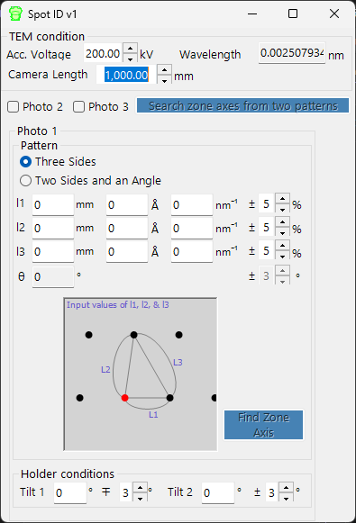
When you do not have an image to load, you can still search for candidate zone axes by entering the geometry of a selected-area electron diffraction (SAED) pattern by hand. Enter the TEM observation conditions and the spot geometry, then press Search zone axes to find candidate crystal orientations.
TEM condition
Enter the TEM observation conditions (acceleration voltage, camera length, etc.).
Photo 1, 2, 3
Enter the geometry of the diffraction spots.
- To enter spot-to-spot distance on the detector, use the mm box.
- If you know the d-value, enter it in Å or nm⁻¹ units.
Three sides mode — Enter the lengths of the three sides of a triangle with the direct spot as one vertex.
Two sides and an angle mode — Enter the lengths of two sides (including the direct spot) and the angle between them.