Structure Viewer
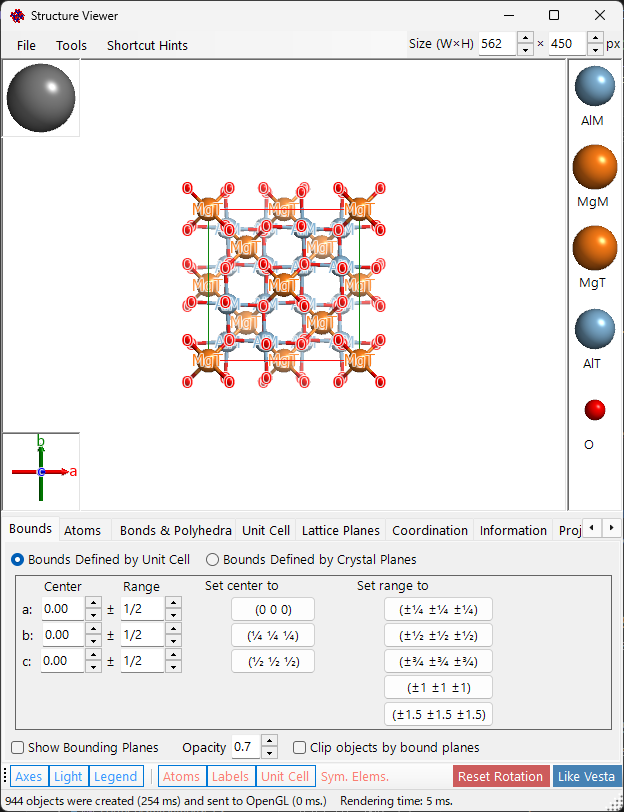
Structure Viewer draws the structure of the selected crystal as a three-dimensional image using OpenGL.
Keyboard & mouse shortcuts
The window has a main 3-D view plus two small gizmos — the crystal-axes box (bottom-left) and the light-direction box (top-left) — and each responds to a left-drag differently. The main view uses ReciPro's standard OpenGL view navigation.
| Shortcut | Action |
|---|---|
| F1 | Open this page of the online manual |
| CTRL+SHIFT+C | Copy the rendered image to the clipboard |
| Left-drag the main view | Rotate the model |
| Left double-click an atom | Show its coordinates, nearest-neighbour distances, and bond angles |
| Right-drag up/down, or Mouse wheel | Zoom |
| Middle-drag | Pan |
| CTRL + Right-drag up/down | Change the camera distance (perspective mode only) |
| CTRL + Right double-click | Toggle orthographic / perspective projection |
| Left-drag the crystal-axes gizmo | Rotate the model (no in-plane spin) |
| Left-drag the light gizmo | Change the lighting direction |
The application-wide CTRL+SHIFT shortcuts from the main window also work while this window is focused.
→ See 21. Keyboard & mouse shortcuts for every window at a glance.
Main area
The 3-D crystal structure, drawn together with the light-direction gizmo, the crystal-axes gizmo and the atom legend.
The Size (W×H) box at the top right of the window sets the pixel size used when saving or copying the rendered image. The ProjWidth box next to it shows the width of the projected view in nm. Edit the value to zoom numerically — it stays synchronized with right-drag / wheel zooming on the view.
Menu bar

File menu
| Menu item | Description |
|---|---|
| Save Image | Save the rendered image to a file |
| Copy Main Image to Clipboard | Copy the image (Ctrl+Shift+C also works) |
| Save Movie | Save a rotation/translation movie as MP4 (speed, duration, fps, quality and so on) |
| Export 3D Model (3MF/STL) | Write the displayed structure out as a solid model for 3D printing |
| Shortcut Hints | Show the keyboard shortcuts |
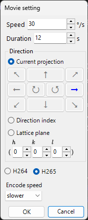
Save movie opens the Movie setting dialog below. A movie can rotate the view, translate the projection center, or do both at once — tick Rotation and/or Translation:
- Rotation: rotates the view at Speed (°/s; negative values reverse the direction) about the axis chosen below — Current projection (tilt direction picked with the arrow buttons), a Direction index [uvw], or the normal of a Lattice plane (hkl).
- Translation: moves the projection center along the direction index [uvw] at Speed (lattice periods per second). This option appears only when the dialog is opened from the Structure Viewer, and while it is enabled Direction index is the only direction mode.
Set the movie length (Duration), the frame rate (FPS, 1–120), and the encoder quality (Quality, 1–100; higher values use a higher bitrate and give a larger file), choose the codec (H264 / H265), and press OK to generate an MP4 file. Include final frame appends one extra frame at t = Duration so the movie ends exactly at the final orientation/position. (The encode-speed list only labels the progress display and no longer affects the actual encoding.)
Export 3D Model (3MF/STL)
Export 3D Model (3MF/STL) writes the structure currently drawn on screen out as a solid model for 3D printing. Only closed solids can be exported — atoms (spheres and ellipsoids), bonds (cylinders) and coordination polyhedra. Atom labels, bound planes and lattice planes cannot be printed and are ignored. The unit cell frame is made of line segments, so it is replaced by cylinders (with spheres at the corners) only when you tick the corresponding option.
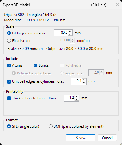
The top of the dialog reports the number of objects and triangles involved, and the real size of the model (Model size, nm).
Scale : how the output size is decided
- Fit largest dimension : scales the model automatically so that its longest edge reaches the length you give (5–500 mm, 80 mm by default).
- Fixed scale : give the scale (mm/nm) directly. Use this to build several crystals at the same scale so they can be placed side by side. Switching to it starts from the scale that was in effect a moment before.
- The line below shows the resulting scale and the printed dimensions (Output size, mm).
Include : which elements go into the print
- Atoms / Bonds / Polyhedra : only the kinds currently displayed can be selected; unticking one keeps it on screen but leaves it out of the print.
- Polyhedra: solid faces / edges, dia. : export coordination polyhedra either as solid bodies with faces, or as an edge frame (cylinders plus spheres at the vertices, 2.0 mm by default). The frame leaves the atoms inside visible.
- Unit cell edges as cylinders, dia. : include the unit cell frame, replaced by cylinders of the given diameter (2.4 mm by default).
Printability : print soundness
- Thicken bonds thinner than : bonds whose printed diameter would fall below the given value (1.2 mm by default) are rebuilt at that diameter from the original primitive. This keeps thin bonds from snapping. If you leave it off while a bond is too thin, a warning appears in red.
Format : file format
- STL (single color) : a single-colour binary STL.
- 3MF (parts colored by element) : 3MF with the parts coloured by element; the colour names carry the element names.
Save... asks for the file name. Once the export finishes, the triangle count, printed dimensions and scale are logged in the information box at the bottom left.
Tab menu
Bounds defined by cell
Specify the drawing range of the crystal. There are two modes, switched with the radio buttons at the top.
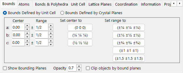
In this mode the a, b, c axes of the unit cell are the unit of the drawing range.
- Center: central fractional coordinate of the drawing volume.
- Range: upper/lower limit for each of the a, b, c axes.
- Preset buttons on the right give frequently used values (e.g. 1×1×1 cell, 2×2×2 cell).
Bounds defined by crystal planes
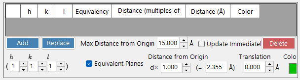
In this mode the drawing area is bounded by a set of crystal planes. If the planes do not define a spatially closed region, ReciPro automatically falls back to a one-unit-cell bound.
Bound list
All bound planes registered for the current crystal. Use Add / Replace / Delete to manipulate the list; the leftmost checkbox temporarily disables a plane without deleting it.
To save the changes permanently, you must also press Add or Replace in the Main Window. Otherwise the changes are lost the next time you change the selection in the main crystal list.
H k l indices
Set the bound plane by its Miller index. The checkbox includes crystallographically equivalent planes generated from the selected (hkl).
Distance from origin
The distance from the centre of the crystal to the bound plane. The unit is selectable between d and Å. With d, the distance is the input value multiplied by the d-spacing of the selected (hkl). With Å, the value is the absolute distance. Changing one updates the other automatically.
Show bound planes / Opacity
Show or hide the bound planes themselves. When shown, Opacity sets transparency (0 = transparent, 1 = opaque).
Clip objects by bound planes
If checked, only the inside region defined by the bounds is rendered; atoms, bonds, and polyhedra that intersect the bounds are clipped.
Hide atoms
If checked, all atoms, bonds, and polyhedra are hidden — useful when only the cell or lattice planes need to be visualised.
Atoms
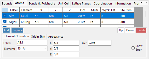
Sets the species, position and occupancy of every atom, and how each one is drawn (radius, colour, material).
Atom list
The list of atoms in the crystal. Use Add / Replace / Delete to manipulate the list; the leftmost checkbox temporarily hides an atom.
To save changes permanently, click Add or Replace in the Main Window as well.
Element & Position
- Label: free-text label for the atom (used in legends and tooltips).
- Element: chemical element / ionisation state.
- X, Y, Z: fractional coordinates. Real numbers in 0–1, or fractions such as
1/2or2/3. - Occ: occupancy, a real number 0–1.
Origin shift

Shifts every atom by the same fractional offset. Press a preset button (for example, to swap origin choice 1 / 2 for the same space group), or enter a custom (Δx, Δy, Δz) and press Apply custom shift.
Appearance

Per-atom radius, colour, and material.
- Radius: drawn atomic radius.
- Atom color: surface colour.
- Material: texture / material properties used by the OpenGL shader.
- Apply to same elements: applies the current radius and colour to every atom of the same element species.
Bonds & Polyhedra
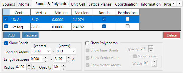
Defines which atom pairs are bonded (by species and distance range) and how the resulting bonds and coordination polyhedra are drawn.
Bond list
All bond/polyhedron rules registered for the crystal. Use Add / Replace / Delete; the leftmost checkbox temporarily disables an entry. As with atoms and bounds, Add / Replace in the Main Window is required to make the change permanent.
Bond property
- Bonding Atom (center): element species used as the centre atom of the bond / polyhedron.
- Bonding Atom (vertex): element species used as the vertex (the other end).
- Length between … and …: lower and upper distance thresholds. Atom pairs outside this range are not drawn.
- Bond Radius: drawn bond thickness (cylinder radius).
- Alpha: bond transparency (0 = transparent, 1 = opaque).
Polyhedron property
- Show Polyhedron: when checked, the polyhedron defined by the current bond is drawn (only if the centre/vertex set is geometrically valid).
- Inner Bonds: show/hide the bonds inside the polyhedron.
- Center Atom: show/hide the centre atom.
- Vertex Atoms: show/hide the vertex atoms.
- Color / Alpha: face colour and transparency.
- Show Edges: draw the edges connecting the vertices.
- Edge Color / Width: colour and line width of the edges.
Unit Cell
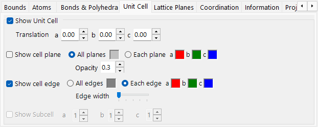
Sets the position of the drawn unit cell and whether its faces and edges are shown.
Translation
Every space group has a default origin. To move the centre of the drawn unit cell away from that origin, set the translation along a, b, c.
Show cell plane
Whether to draw the six faces that bound the unit cell. When enabled, you can set the face colour and transparency.
Show edges
Whether to draw the unit-cell edges. The edge colour is configurable.
Lattice Planes
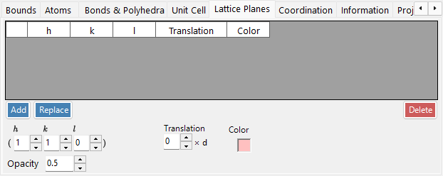
Draws lattice planes given by their Miller index, optionally including the crystallographically equivalent planes.
H k l indices
Specify the lattice plane by its Miller index. The checkbox optionally includes crystallographically equivalent planes generated from (hkl).
Translation
Translate the drawn lattice plane by an integer multiple of its d-spacing — useful for visualising successive planes of the same family.
Coordination
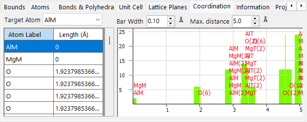
Lists and plots the atoms coordinating a chosen target atom.
Table (left side)
Lists which atoms surround the selected target atom and at what distance. The target atom is selected from the dropdown above the table.
Graph (right side)
Histogram of neighbour count versus distance, derived from the same data as the table. Adjust Bar Width until the bars cleanly separate the coordination shells — this gives a visual estimate of the coordination number.
Information
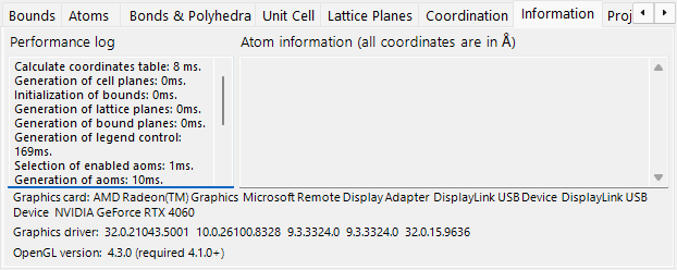
Rendering log (frame time, GPU info) and basic information about the selected atom. Under construction — fields may grow over time.
Projection
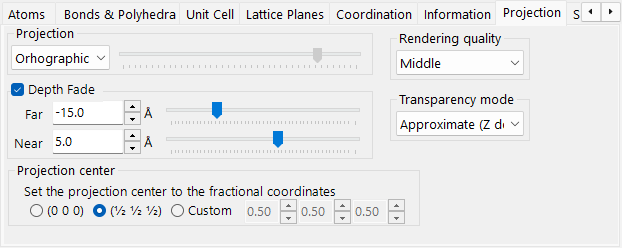
Sets the projection mode (orthographic / perspective), depth fading, the projection centre, the rendering quality and the transparency algorithm.
Projection
- Orthographic: perfect parallel projection (viewpoint at infinity).
- Perspective: perspective projection from the viewpoint distance set by the slider.
Depth fading out
Fades distant objects in the depth direction. Objects farther than Far are fully transparent; objects closer than Near are fully opaque; intermediate objects interpolate linearly.
Projection center
Sets the centre of projection to the specified coordinates. Turn on Custom to enter arbitrary coordinates. Each coordinate is folded into the range −0.5 to +0.5 (one lattice period). A Translation movie (see the File menu) drives these values automatically.
Rendering quality
Drawing quality (mesh subdivision, anti-aliasing). Higher quality is slower — choose the setting that matches your GPU.
Transparency mode
Algorithm used for translucent atoms and polyhedra.
- Approximate: fast but can be inaccurate when many translucent objects overlap.
- Perfect: order-independent transparency — accurate but very slow, effectively requires a discrete GPU.
Symmetry Elements
The Symmetry Elements tab draws the space-group symmetry operators directly onto the 3D model (toggle with the Symmetry Elements toolbar button). Each class of element can be shown/hidden independently:
- Rotation axes and screw axes
- Mirror planes and glide planes
- Inversion centres and rotoinversion axes
For each class you can adjust the symbol size, line width, and colour.
Misc.
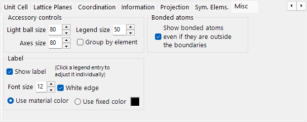
- Accessory controls: set the display sizes (light ball, axes, legend). Group by element toggles the legend display.
- Bonded atoms: Show bonded atoms even if they are outside the boundaries keeps drawing atoms that are bonded to atoms inside the drawing range, even when they fall outside it.
- Label: set the font size, colour, and other properties of the atom labels.
Toolbar

| Button | Description |
|---|---|
| Axes | Show axis orientation (size = lattice constant) |
| Light | Set light direction |
| Legend | Atom legend |
| Atoms | Toggle atom objects |
| Labels | Toggle atom labels |
| Unit Cell | Toggle unit-cell edges |
| Sym. Elems. | Toggle the symmetry-element overlay (see above) |
| Reset Rotation | Return to the initial orientation |
| Like Vesta | Switch to a VESTA-style appearance (atom colours and radii) |