Appendix A1.1. Basic coordinate system and crystal orientation
This page defines ReciPro's basic (orientation) coordinate system, used everywhere crystal rotation is involved (Main window, Structure Viewer, Stereonet, Rotation Geometry, and diffraction simulation), together with how a crystal's initial orientation and Euler-angle rotation are expressed. The separate system used to place the detector in Crystal Diffraction is described in A1.2. Coordinate system for diffraction simulation.
Definition of orientation
ReciPro uses a right-handed coordinate system fixed to the monitor:
| Axis | Direction |
|---|---|
| \(X\) | Right of the monitor |
| \(Y\) | Upward on the monitor |
| \(Z\) | Vertically out of the monitor, toward the viewer |
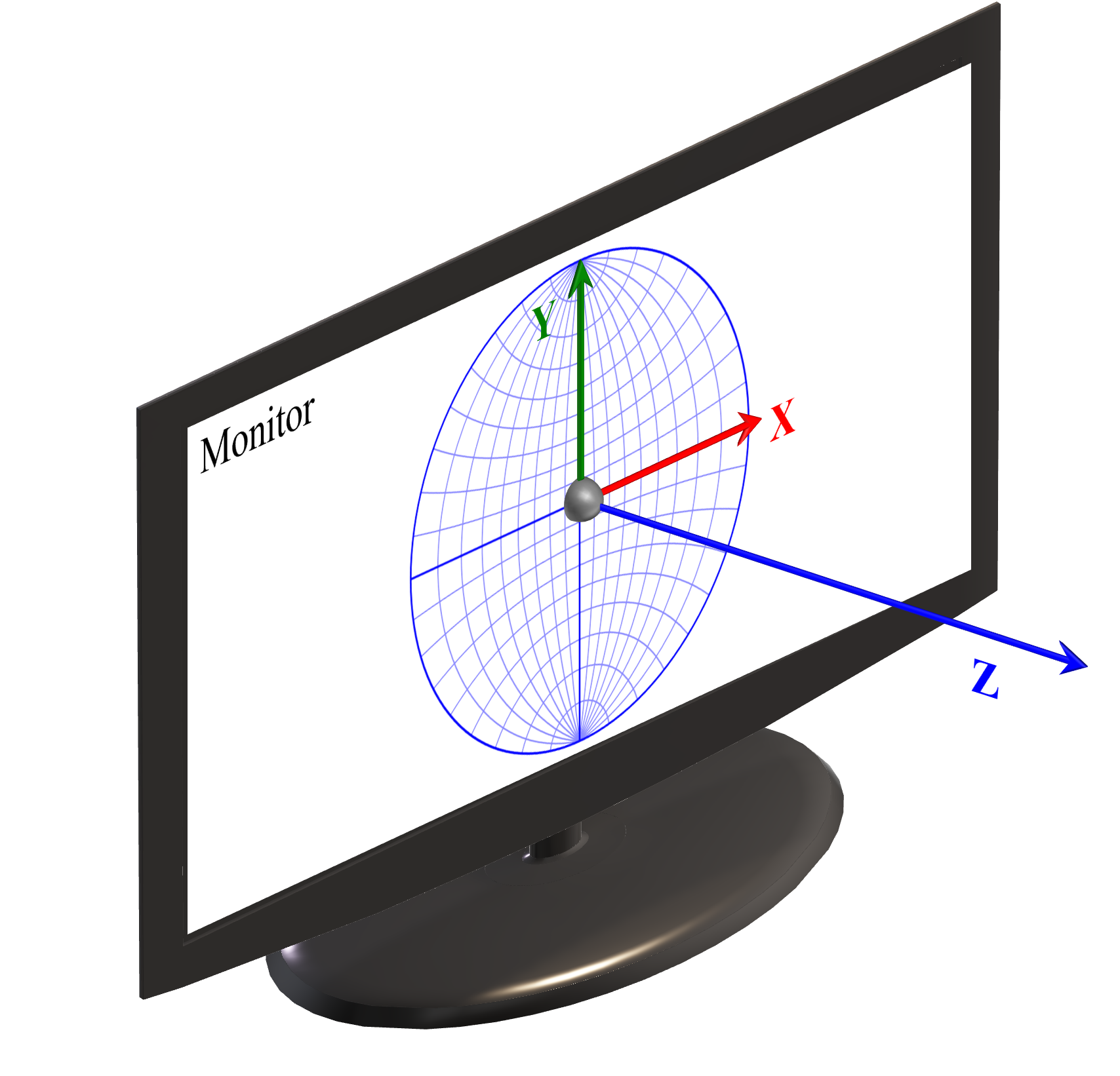
The beam direction corresponds to the viewing direction (looking into the monitor), i.e. the \(-Z\) axis.
Most operations in ReciPro involve only directions (expressed as 3×3 rotation matrices) and do not require an explicit origin. The one exception is the Crystal Diffraction function, which needs an explicit origin — see A1.2. Coordinate system for diffraction simulation.
Initial crystal direction
The initial orientation (at first launch, or after Reset rotation) is defined as:
- The \(c\)-axis is aligned with the \(Z\)-axis.
- The \(b\)-axis lies in the \(Y\)\(Z\) plane, close to the \(Y\)-axis.
- The \(a\)-axis is then fixed by the \(b\)- and \(c\)-axes (right-hand rule).
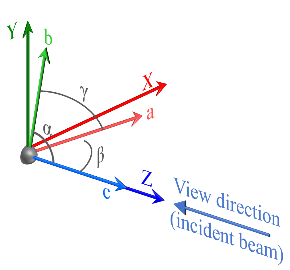
Equivalently:
- The direction out of the monitor (toward the viewer) is the [001] zone axis.
- The rightward direction on the monitor is the normal of the (100) plane.
Note: The \(c\)-axis (= [001]) always coincides with \(Z\), but in some crystal systems the \(a\)- and \(b\)-axes do not necessarily coincide with \(X\) and \(Y\).
Euler angles
Crystal orientation is expressed with three Euler angles \(\Phi\), \(\theta\), \(\Psi\), applied in \(Z\)–\(X\)–\(Z\) order (\(\Psi\), then \(\theta\), then \(\Phi\)). When all three angles are zero, the corresponding rotation axes are:
| Angle | Axis (when all angles = 0) | Rank |
|---|---|---|
| \(\Phi\) | \(Z\) | 1st (highest) |
| \(\theta\) | \(X\) | 2nd (middle) |
| \(\Psi\) | \(Z\) | 3rd (lowest) |
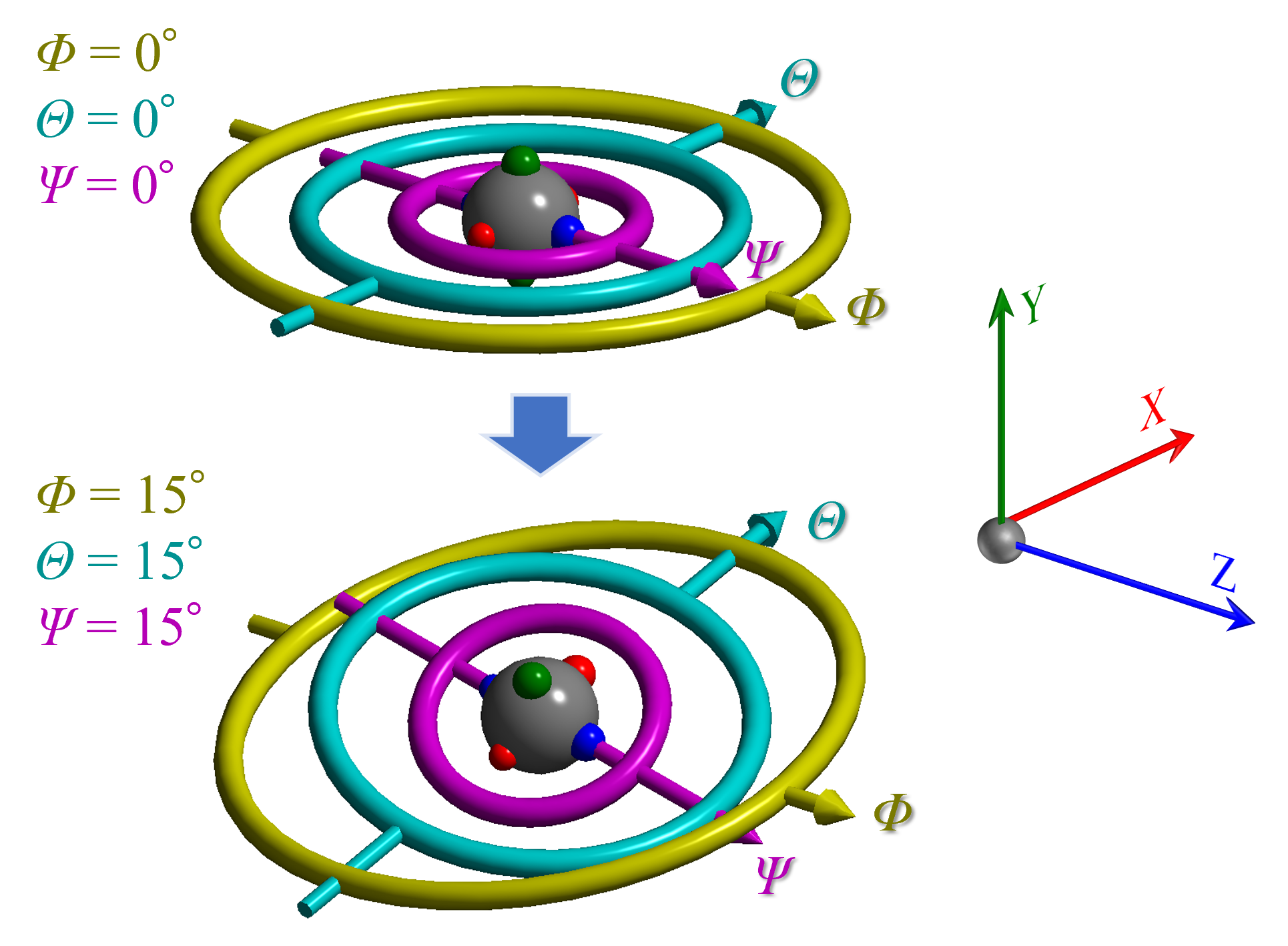
The three angles form a hierarchy: \(\Phi\) is the highest rotation, followed by \(\theta\), then \(\Psi\). The direction of a lower axis depends on the state of the higher rotations. For example, when \(\Phi\) = \(\theta\) = \(\Psi\) = 15°, the \(\Phi\) axis still coincides with \(Z\), but the \(\theta\) and \(\Psi\) axes generally align with none of \(X\), \(Y\), or \(Z\).
The Rotation Geometry window can re-express this orientation in an arbitrary, experiment-specific Euler-angle convention (e.g. to match a laboratory goniometer). See 4. Rotation Geometry.