Appendix A1.2. Coordinate system for diffraction simulation
The Crystal Diffraction function simulates the diffraction pattern recorded on a detector. The detector is a finite plane of pixels placed at a fixed distance from the sample, and it may be tilted with respect to the incident beam. Reproducing this accurately requires the geometric relationship between the detector and the sample, together with the detector's pixel size and pixel count. For the basic (orientation) coordinate system, see A1.1. Basic coordinate system and crystal orientation.
Z and Y differ from the orientation system
Within the detector coordinate system, \(Z\) is parallel to the beam and \(Y\) points downward. This differs from the orientation coordinate system, where the beam is along \(-Z\) and \(Y\) points up. The detector system follows the usual image/detector convention (origin at the top-left, \(Y\) increasing downward).
Before rotation (detector normal to the beam)
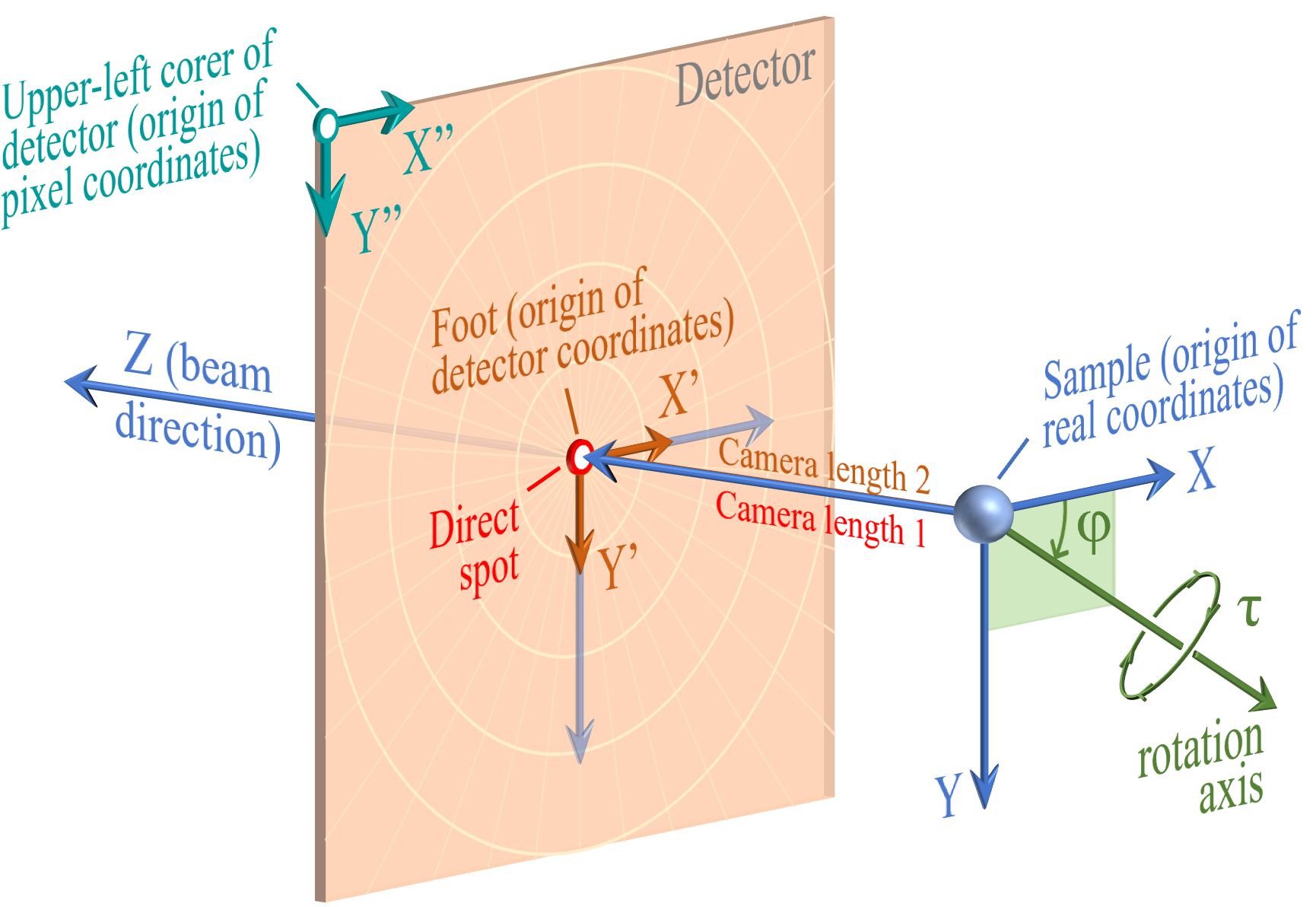
Three coordinate systems are defined:
- Real coordinates (\(X\), \(Y\), \(Z\)) : 3D Cartesian coordinates in mm, with the sample as origin. \(Z\) is parallel to the beam; viewed along \(Z\), \(X\) points right and \(Y\) points down. When the detector is normal to the beam, \(X\) / \(Y\) are parallel to \(X'\) / \(Y'\).
- Detector coordinates (\(X'\), \(Y'\)) : 2D coordinates in mm on the detector plane, with the foot as origin. \(X'\) / \(Y'\) point right / down on the detector and are parallel to \(X''\) / \(Y''\).
- Pixel coordinates (\(X''\), \(Y''\)) : 2D coordinates in pixel units, with the upper-left corner of the detector as origin, following the detector's pixel rows and columns.
When the detector is perpendicular to the beam, the foot and the direct spot coincide, and Camera length 1 equals Camera length 2.
After rotation (tilted detector)
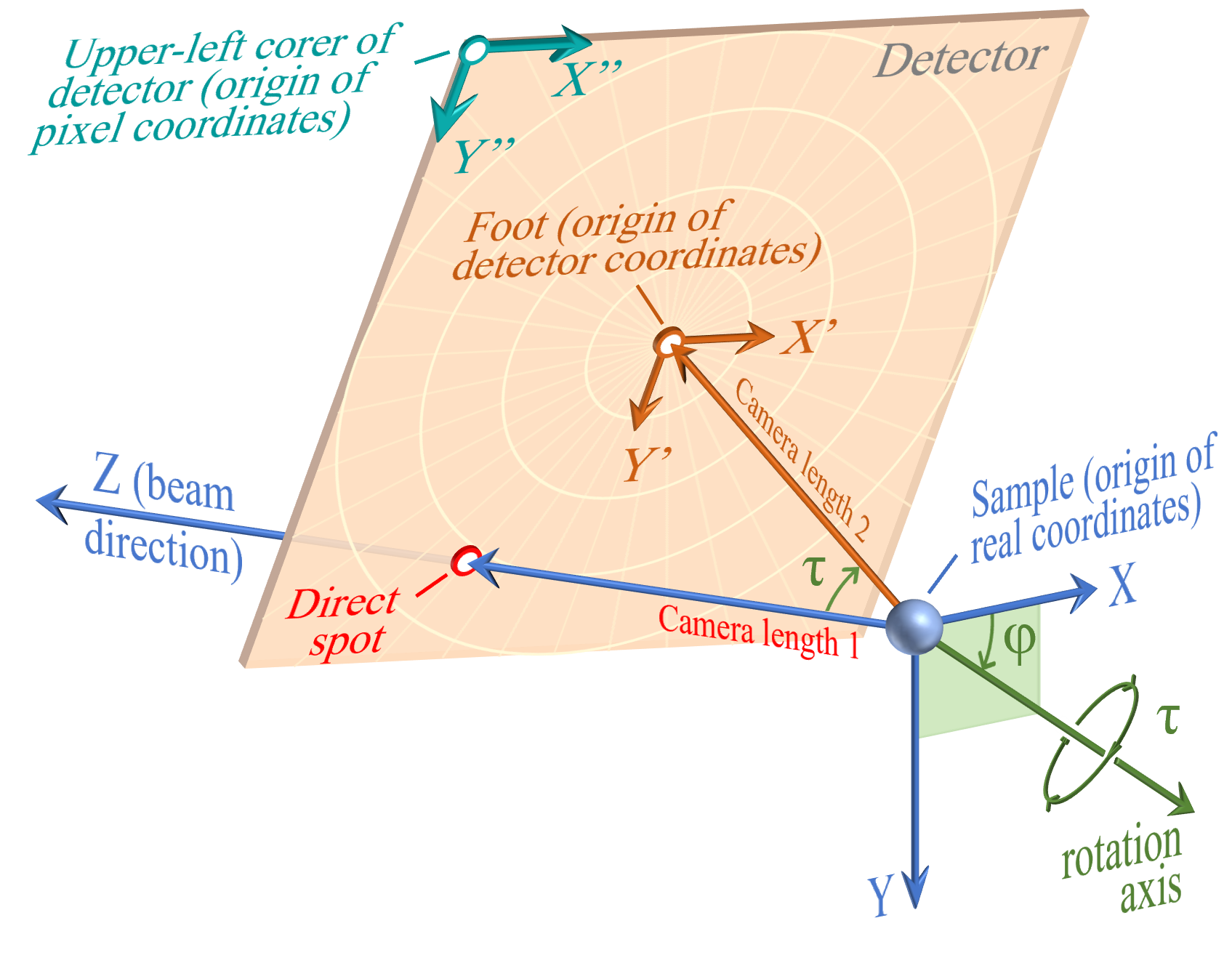
The detector tilt is described by two parameters:
| Parameter | Description |
|---|---|
| \(\varphi\) | Direction of the rotation axis — its angle from the \(X\)-axis, measured in the \(XY\) (\(Z\) = 0) plane |
| \(\tau\) | Rotation angle about that axis (right-hand screw) |
Once the detector is tilted:
- The direct spot and the foot no longer coincide.
- Camera length 1 (\(C_1\)) = distance from the sample to the direct spot.
- Camera length 2 (\(C_2\)) = distance from the sample to the foot.
- The origin of Detector coordinates stays at the foot; the origin of Pixel coordinates stays at the upper-left corner.
- The \(X\) / \(Y\) directions no longer coincide with \(X'\) / \(Y'\).
Parameter glossary
| Term | Definition |
|---|---|
| Sample | The material scattering the incident beam; the origin of the real coordinates |
| Real coordinates (\(X\), \(Y\), \(Z\)) | 3D coordinates (mm) of the experimental setup; origin at the sample, \(Z\) always parallel to the beam |
| Direct spot | Intersection of the incident beam and the detector |
| Foot | The foot of the perpendicular from the sample to the detector plane; origin of the detector coordinates. Coincides with the direct spot only when the detector is normal to the beam. For overlay-image mode, set the foot position in pixel coordinates |
| Detector coordinates (\(X'\), \(Y'\)) | 2D coordinates (mm) on the detector plane; origin at the foot |
| Pixel coordinates (\(X''\), \(Y''\)) | 2D coordinates (pixels) on the detector plane; origin at the upper-left corner |
| Camera length 1 (\(C_1\)) | Distance from the sample to the direct spot (mm) |
| Camera length 2 (\(C_2\)) | Distance from the sample to the foot (mm) |
| Pixel size | Side length of one (square) pixel (mm); only square pixels are supported |
| Detector width / height | Number of pixels horizontally / vertically |